How Current Actually Works?
What is Electric Current?
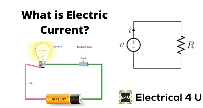
Electric current is the flow of electric charge. It refers to the flow of electrons in a conducting wire or other material. Electric current is measured in amperes, which measures the rate of flow of the charge.
More specifically, electric current is the rate at which charge passes through a given point in an electrical circuit. It’s caused by the movement of electrically charged particles, usually electrons. The particles move from a region of higher electric potential energy to one of lower electric potential energy. The greater the electric potential difference between two points, the greater the electric current between them when they are connected by a conductor.
Electric Charge
Electric charge is a fundamental property of matter that exists in the form of positively or negatively charged particles. Atoms contain subatomic particles called protons and electrons that carry electric charges.
Protons have a positive electric charge (+), while electrons have a negative electric charge (-). The charges of protons and electrons are equal in magnitude but opposite in sign. Atoms are electrically neutral when they contain an equal number of protons and electrons.
When there is an imbalance between the number of protons and electrons, an atom acquires a net electric charge and is called an ion. A net excess of electrons results in a negative charge, while a net lack of electrons results in a positive charge.
Electric charge is measured in a unit called the coulomb (C). Protons and electrons each have an electric charge of -1.602 x 10⁻¹⁹ C.
Electric Potential Difference
Electric potential difference, also known as voltage, refers to the difference in electric potential energy between two points in an electric circuit. It is measured in volts. Electric potential difference is created by devices such as batteries, generators, solar cells, thermocouples, or dynamos.
Within a circuit, electrons flow from a point of higher potential energy (the negative terminal of the battery) towards a point of lower potential energy (the positive terminal). As they move, the electrons lose potential energy and gain kinetic energy. The greater the potential difference between two points, the greater the force pushing electrons from the negative to the positive terminal.
Potential difference is required for current to flow in a circuit. Without a potential difference, electrons would have no reason to flow in a particular direction. The higher the voltage or potential difference, the greater the electric current as more electrons flow through the circuit.
Conductors and Insulators
All materials can be classified into two categories based on how they conduct electricity: conductors and insulators. The difference between these two classifications comes down to how they respond to an applied voltage or electric field.
Conductors are materials that allow the flow of electric current. They contain mobile electric charges that are free to move around within the material. When an electric voltage is applied, the charges in the conductor are able to move and carry electric current. This motion of charges is what makes electric power and signals possible. Metals like copper and aluminum are common examples of good conductors.
Insulators are materials that resist the flow of electric current. They do not contain mobile electric charges that can move freely. When voltage is applied, the fixed charges in the insulator are not able to flow and carry current. This makes them very useful for preventing current leakage and electrically isolating different parts of electrical systems. Common insulators are materials like plastic, glass, and rubber.
Understanding the difference between conductors and insulators is key to many electrical engineering principles and designing safe and effective electrical systems. The combination of carefully placed conductors and insulators allows us to control the flow of electricity.
Ohm’s Law
Ohm’s law describes the relationship between current, voltage, and resistance in electrical circuits. It states that the current (I) through a conductor is directly proportional to the voltage (V) applied, and inversely proportional to the resistance (R). This can be written mathematically as:
I = V/R
Where I is the current in amps, V is the voltage in volts, and R is the resistance in ohms. This means that for a given voltage, higher resistance results in less current, while lower resistance allows more current to flow. Similarly, increasing the voltage across a fixed resistance increases the current through it. Ohm’s law is a simple but powerful formula that forms the basis of circuit analysis.
Direct Current vs Alternating Current
Electric current comes in two main forms: direct current (DC) and alternating current (AC). They differ in the direction that the electricity flows.
Direct current flows in one direction only. The electrons move from the negative terminal to the positive terminal of a power source, such as a battery. Appliances powered by DC current include automobiles, phone chargers, and solar panels.
Alternating current periodically changes direction back and forth. The electrons flow first in one direction, then switch to the opposite direction at regular intervals. Most power plants and household outlets provide AC current. Devices like lights, televisions, computers use AC because it is easier to increase or decrease the voltage for transmission over long distances.
So in summary, DC provides a constant voltage or current, while AC alternates between positive and negative values. DC is better for small, low voltage applications, while AC can transmit power across far distances through transformers.
Series vs Parallel Circuits
Circuits can be arranged in two basic configurations: series and parallel. The main difference between series and parallel circuits is how the components are connected.
In a series circuit, there is only one path for current to flow through all the components. The components are connected end-to-end in a single loop. The current passing through each component is the same. The total resistance in the circuit is the sum of the individual resistances. If one component fails and breaks the circuit, current will cease to flow through all components. Examples of series circuits include Christmas tree lights – where if one light goes out, all the lights go out.
In a parallel circuit, the components are connected side-by-side in branches off the main circuit. This creates multiple paths for current to flow. The voltage across each component is the same, but the currents through the branches can be different. The total resistance in the circuit is decreased. If one component fails, current continues to flow through the other branches. Examples of parallel circuits include wiring in households and lighting circuits.
The main advantage of a series circuit is simplicity, while parallel circuits provide redundancy and reduced resistance. Engineers take advantage of both types of circuits when designing electrical systems.
Resistors
Resistors are devices that are designed to resist the flow of electric current. Resistors have a specific resistance value, measured in units called ohms (and represented by the Greek letter Omega Ω), that determines how much they resist current flow. According to Ohm’s law, the current through a resistor is equal to the voltage applied across the resistor divided by the resistance. So the higher the resistance of a resistor, the less current will flow through it for a given voltage.
The most common type of resistor used in electronics is the carbon composition resistor. These are small cylindrical components with two electrical leads. Carbon resistors contain a carbon film or paste inside to provide the desired resistance. Other types of resistors include wire-wound resistors, made by winding a metal wire around an insulating core, and metal oxide film resistors made by depositing a thin film of oxidized metal on a ceramic core.
Resistors are passive components – they do not require any power to generate resistance. Instead they dissipate electrical power in the form of heat when current flows through them. Resistors are used extensively in electronic circuits to limit current, divide voltages, and bias active components like transistors. By combining multiple resistors in different configurations, more complex resistor networks can be created for applications like voltage dividers and current limiters.
Capacitors and Inductors
Capacitors and inductors are two important components used in electrical circuits. While resistors simply oppose current flow, capacitors and inductors store and release energy in electric and magnetic fields.
Capacitors
Capacitors are components that store energy in an electric field. They consist of two conducting plates separated by an insulating material or dielectric. When connected to a power source, electric charges of equal magnitude but opposite polarity build up on each plate. One plate gains a positive charge and the other a negative charge, creating an electric field between the plates. The electric field allows the capacitor to store energy.
The amount of energy a capacitor can store depends on its capacitance, which is a measure of the capacitor’s ability to store charge for a given voltage applied. Capacitors are useful for filtering signals, tuning circuits, and storing energy. They are found in nearly every modern electronic device.
Inductors
Inductors are coils of wire that store energy in a magnetic field. When current passes through an inductor, it creates a magnetic field around the coils. The magnetic field induces a back EMF (voltage) in the inductor that opposes the current change. This property of inductors makes them resist changes in current.
The energy stored in an inductor’s magnetic field depends on the inductance, which depends on the number of coils and material properties. Inductors are used for filtering, oscillation, and energy storage in circuits. They are found in power supplies, radios, and motors.
Applications of Electric Current
Electric current has many essential applications in modern technology and devices:
Electronics – Current is used to power and control electronic components like transistors, integrated circuits, sensors, etc. Modern electronics permeate countless aspects of daily life.
Motors – Electric motors convert electrical energy into mechanical energy. They use current and magnetic fields to generate force and motion to power fans, pumps, tools, electric cars, etc.
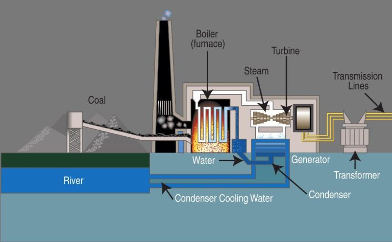
Generators -Generators convert mechanical energy into electrical energy. Using electromagnetic induction, generators produce voltage from motion to generate electric current.
Household Appliances – Most appliances like refrigerators, microwaves, vacuums, etc. require electric current to operate motors, heaters, lights, or electronic controls.
Without harnessing the flow of electric charge, today’s technology-driven world would not be possible. Electric current powers and enables the modern conveniences and innovations we rely on.