What Is The Direction Of Electric Energy?
Electric energy refers to the flow of electrons through a conductor such as a wire or transmission line. It is a form of energy that can be generated at power plants and then distributed for residential, commercial and industrial uses. Understanding the direction of electric energy flow is crucial for operating electrical systems safely and efficiently.
Electrons flow from areas of high potential energy to areas of low potential energy. This electron flow is what we call electricity or electric current. The direction of electron flow is from negative to positive potential, which is the opposite of conventional current direction that flows from positive to negative. While electron flow is the actual movement of charges, conventional current is an imagined flow used for circuit analysis.
Knowing about electron flow versus conventional current helps understand hazards like shocks and short circuits. The direction of current also impacts how loads are wired and how protection systems operate. Overall, being aware of electricity’s direction provides a foundational knowledge for working with electrical systems and components.
Electricity Generation
Electricity is generated from a variety of energy sources such as coal, natural gas, nuclear, hydropower, solar, wind, geothermal, biomass, and other renewables. At power plants, the potential energy stored in these sources is converted into electrical energy through various processes:
– Fossil fuel plants like coal, oil, and natural gas plants burn these fuels to boil water into steam that spins a turbine connected to a generator to produce electricity.
– Nuclear power plants use nuclear fission reactions to heat water into steam that spins a turbine-generator.
– Hydropower plants use flowing water from reservoirs or dams to spin hydro turbines connected to generators.
– Wind turbines use wind to spin blades connected to generators and produce power.
– Solar photovoltaic panels convert sunlight directly into electricity using semiconductors.
– Geothermal plants tap into underground heat to produce steam for spinning turbine-generators.
– Biomass plants burn plant and animal waste as fuels to boil water into steam to spin turbines.
The electrical energy that is generated is then fed into the transmission grid and distributed for end use.
Transmission Grid
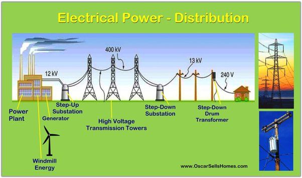
The transmission grid is the interconnected network of high-voltage transmission lines that transport electricity over long distances from power plants to substations. The transmission system in North America consists of about 300,000 km of lines operated by independent system operators or utilities.
Power plants generate electricity at low voltages. Step-up transformers located at power plants increase the voltage to hundreds of thousands of volts for efficient transmission over long distances. This allows the transmission lines to carry large amounts of power with lower losses. The high voltage enables the current to flow with less resistance in the wires.
Most transmission lines use three-phase alternating current (AC). The three phases allow more power to be transmitted in a smaller space. Aluminum conductor steel reinforced cable (ACSR) is commonly used for overhead transmission lines due to its high tensile strength and conductivity. Underground and underwater cables use materials like cross-linked polyethylene for insulation.
Transmission networks are built with redundancy and interconnectedness to ensure reliable delivery of electricity. If one line fails, power can be rerouted. Protection systems rapidly isolate faults. The grid is designed and operated to withstand extreme events while maintaining operation.
Step-Up Transformers
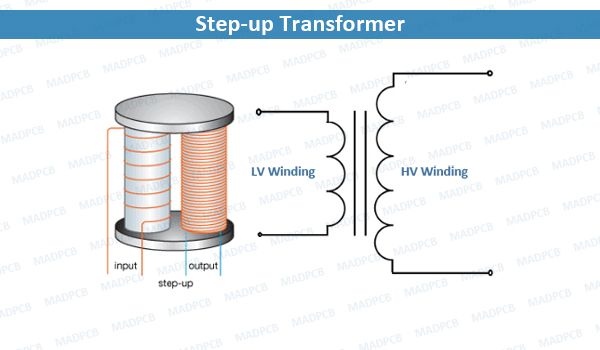
Step-up transformers play a crucial role in the transmission of electricity over long distances. They increase, or step up, the voltage output of a generator before electricity enters the transmission system. This step-up in voltage enables the efficient transmission of electricity across a power grid.
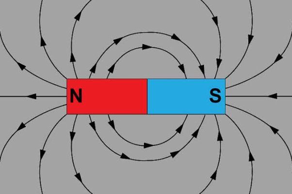
Transformers work on the principle of magnetic induction between coils of wire. Step-up transformers have a primary coil connected to the electricity source and a secondary coil with a greater number of turns. This increased number of turns in the secondary coil induces a higher voltage in that coil. For example, a step-up transformer can increase the voltage from a generator from around 20,000 volts to as high as 500,000 volts for transmission.
The reason such a dramatic step-up in voltage is necessary has to do with the physics of transmitting electricity over long distances. Higher voltage electricity can be transmitted more efficiently over long distances, resulting in lower transmission losses. This is because higher voltages allow lower currents for the same amount of power transmission. Since power losses are proportional to the square of current, increasing voltage significantly reduces these resistive losses along transmission lines.
Step-up transformers are thus a key enabling technology for efficient long-distance transmission of electricity from distant generation sites to load centers. Their ability to dramatically increase voltage makes it feasible and economical to transmit electricity across hundreds of miles.
Step-Down Transformers
To reduce the high voltage electricity from transmission lines down to lower and safer levels for distribution, step-down transformers are used. Step-down transformers work through electromagnetic induction to convert the incoming high voltage electricity to a lower outgoing voltage.
Inside a step-down transformer are two coils of wire called the primary coil and secondary coil. The primary coil is connected to the incoming high voltage electricity from the transmission lines. When electricity flows through the primary coil, it creates a magnetic field which induces a current in the secondary coil.
By having more windings in the primary coil than the secondary coil, the voltage can be stepped down. For example, if the primary coil has 1000 windings and the secondary has 100, the voltage will be stepped down by a factor of 10. This allows incoming electricity at say 115,000 volts to be output at a more usable 11,500 volts.
The step-down transformer is a key component that enables the high voltage electricity from transmission to be transformed into the lower voltages needed for safe and practical distribution to homes and businesses.
Distribution Lines
Distribution lines are the final leg of the electrical energy delivery system, carrying electricity from local substations to homes, businesses, and other end users. These lines distribute power at lower voltages than the high-voltage transmission lines that bring electricity from power plants to substations.
The most common distribution voltages in the U.S. are 12,000 volts and 4,160 volts for systems that eventually supply 120/240-volt residential customers. Industrial customers may receive higher distribution voltages. Underground distribution lines are insulated copper or aluminum cables buried beneath the street or ground. Overhead distribution lines utilize uninsulated aluminum conductors strung between poles.
Distribution system equipment like transformers and switches reduce the transmission voltage down to the final utilization voltage needed by customers. The distribution system includes many branches and circuits to reach widespread end users. Sophisticated monitoring and switching equipment helps identify and isolate faults to maintain reliable service. Proper maintenance and vegetation management around lines are also critical for distribution system reliability.
Direction Conventions
When describing electrical current, conventions are used to establish the direction of current flow. These conventions help to standardize discussions and calculations in electrical engineering.
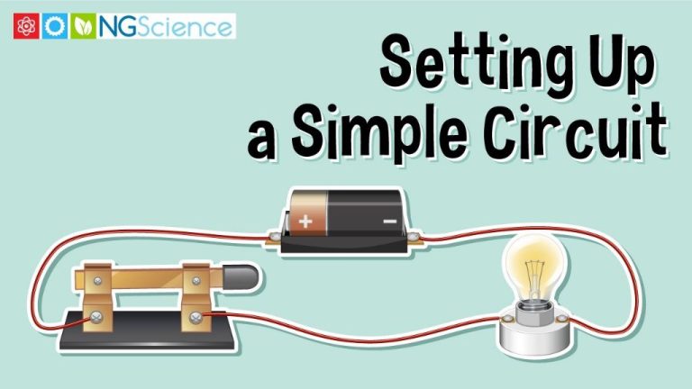
One common convention is the generator convention. This states that the direction of conventional current is taken as flowing from the positive to the negative terminal of the generator or power source. So in a simple circuit with a battery, the current flows from the positive terminal of the battery, through the circuit components, and back to the negative terminal.
Electron flow theory states that electrons move from negative to positive. So electron flow is actually opposite to conventional current flow. However, conventional current direction is still widely used. This generator convention allows current direction to be standardized without needing to consider the movement of electrons.
Other conventions exist as well. In a passive circuit element like a resistor, the passive convention states that the current enters the positive terminal and exits the negative terminal. In an active element like a voltage source, the active convention is used, with current assumed to flow from the element’s positive terminal.
Having standardized conventions allows for consistent analysis of circuit behavior. While the electron flow is physically in the opposite direction of conventional current, the generator convention remains a key concept in electrical engineering.
Measuring Current Direction
There are several pieces of equipment used to precisely measure current direction in electrical systems. Two common options include:
Clamp Meters
Clamp meters are handheld devices that use current transformers or Hall Effect sensors to measure the current flowing through a conductor without having to disconnect it. They clamp around a wire or cable to take a reading.
Modern digital clamp meters will indicate the direction of current flow, shown as positive or negative values on the display. This allows technicians to quickly validate that current is flowing in the expected direction.
Directional Current Relays
Directional overcurrent relays contain directional elements that can determine the direction of current flow. They operate based on the phase angle between voltage and current waveforms.
These relays are used to initiate the tripping of circuit breakers and opening of switches when current flows in an abnormal or undesired direction, providing protection and selectivity.
Understanding current direction is crucial for proper installation, operation, and protection of electrical systems. The right test equipment makes it possible to accurately measure and confirm direction.
Direction Importance
The direction of electric current flow is crucial for operating and protecting electrical equipment safely. Here are some key examples of why current direction matters:
Overcurrent Protection: Circuit breakers and fuses are designed to interrupt current flow when it exceeds safe levels. These devices are oriented to open the circuit when current exceeds ratings in a particular direction. If current flowed the wrong way, the overload protection would fail to activate.
Generators: Most generators push current out in only one direction, from the generator terminals to the distribution system. If current tried to flow backwards into the generator, it could damage the equipment. Protective relays monitor direction and will trip the generator offline if reverse current is detected.
Transformers: Transformers are wound to either step voltage up or down in a certain direction. If current flowed the wrong way, the transformer would not function properly and could overheat or experience insulation breakdown. Directional relays provide protection against reverse current.
Switchgear: High voltage circuit breakers and switches are designed to interrupt current in the normal system direction. Abnormal reverse flow could prevent them from operating properly and lead to arcing faults.
Knowing the expected direction of current flow allows engineers to design protection schemes that keep electrical systems safe and reliable. Unexpected reverse current indicates a fault condition that must be isolated quickly.
Conclusion
The direction of electric current has conventionally been defined as the direction that positive charge flows. This was an arbitrary convention made when the electron hadn’t yet been discovered. We now know that negative electrons are the primary charge carrier in electric circuits, which actually flow in the opposite direction to “conventional” current. However, the original convention is still widely used today.
When describing current direction, it’s important to specify whether you are referring to conventional or actual electron flow. The direction can impact calculations and measurements. However, in many cases like DC circuits, the wires are symmetrical so the direction does not matter.
Overall, being aware of current direction conventions allows us to properly interpret and apply various electrical calculations and principles. While the conventions can seem abstract, they provide a consistent system to analyze circuit behavior.