What Is A Fact About Circuits?
Basics of Electric Circuits
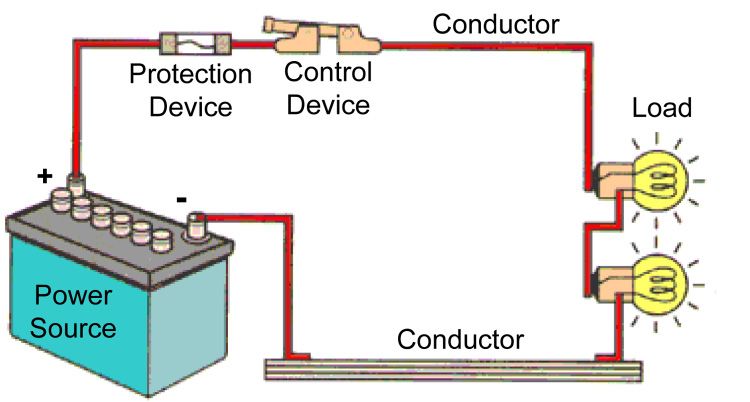
An electric circuit is a closed loop path that electrons follow from a voltage source through various circuit components and back to the voltage source. A basic circuit contains a power source, conductive path, and one or more electrical components like resistors, inductors, capacitors etc. For electrons to continuously flow in a circuit, it must be a complete loop with no gaps. The main characteristics of a circuit are voltage, current and resistance.
Voltage, measured in volts, is the electrical potential energy given by a source like a battery or generator that causes electrons to flow. It can be thought of as the electrical “pressure” pushing electrons to move through a circuit. More voltage leads to more flow of current.
Current, measured in amperes or amps, is the rate of flow of electrons past a point. The higher the current, the more electrons are flowing through the circuit. Current depends on voltage and resistance.
Resistance, measured in ohms, is anything that impedes or restricts the flow of current in a circuit. Resistors deliberately introduce resistance, while the resistance of wires and other components is generally undesired. More resistance reduces the current flow for a given voltage.
These three quantities – voltage, current and resistance – are related by Ohm’s law, which states that current equals voltage divided by resistance (I = V/R). Understanding these basic concepts is key to analyzing any electrical circuit.
Circuit Components
Electric circuits require components that provide unique functions. Some key components found in circuits include:
Batteries
Batteries supply electric current to a circuit. They convert chemical energy to electrical energy through chemical reactions. Common battery types are alkaline, lithium-ion, and lead acid.
Wires
Wires electrically connect the components in a circuit. They are made of conductive materials like copper and carry electric current through the circuit.
Resistors
Resistors limit and regulate the flow of electric current. They add resistance to a circuit which reduces the current. Resistors can provide protection, control signal levels, and divide voltages.
Capacitors
Capacitors store electric charge temporarily. They can smooth out spikes in current and are used for filtering signals. Capacitors block DC current but allow AC current to pass.
Inductors
Inductors use coils of wire to create magnetic fields that store energy. They can filter signals and impede changes in current. Inductors allow DC current but block AC current.
Transistors
Transistors control the flow of current and can act as switches or amplifiers. They are semiconductor devices that are the fundamental building block of modern electronics.
Series vs Parallel Circuits
In electrical circuits, components can be arranged in two main configurations: series or parallel. The difference between these two affects how current and voltage behave.
In a series circuit, electrical components are connected end-to-end in a chain. The current passes through each component in sequence. In this arrangement, the current remains the same at each point of the circuit, but the voltage divides across each component. The total voltage equals the sum of the voltage drops across each individual component.
In a parallel circuit, electrical components are connected between two common points, so the current can divide and pass through multiple paths simultaneously. The voltage is equal across each component. However, the total current in a parallel circuit is equal to the sum of the currents through each individual branch.
So in summary, in series circuits the current is constant while voltage divides, and in parallel circuits the voltage is constant while the current divides into the branches. This contrasting behavior of voltage and current is an essential distinction between series and parallel configurations.
Ohm’s Law
Ohm’s law describes the relationship between current, voltage, and resistance in electrical circuits. It states that the current (I) through a conductor between two points is directly proportional to the voltage (V) across the two points, and inversely proportional to the resistance (R) between them. This relationship is expressed by the equation:
I = V/R
Where:
- I is the current in amperes
- V is the voltage in volts
- R is the resistance in ohms
Some key points about Ohm’s law:
- It only applies to circuits or circuit elements with a single resistor.
- The current and voltage are directly proportional – if you increase/decrease one, the other increases/decreases proportionally.
- The current and resistance are inversely proportional – if you increase/decrease one, the other decreases/increases proportionally.
- Ohm’s law allows you to calculate any one quantity if you know the other two.
Ohm’s law is a fundamental relationship used to analyze electrical circuits. It provides the basis for calculations in circuit analysis and design. Understanding the interrelationships between current, voltage and resistance as described by Ohm’s law is key for electrical engineers and technicians working with circuits.
Kirchhoff’s Laws
Kirchhoff’s laws are two fundamental laws that deal with the current and voltage in electrical circuits. They were formulated by German physicist Gustav Kirchhoff in 1845.
Kirchhoff’s Current Law (KCL)
Kirchhoff’s current law (KCL) states that the total current entering a junction or node in a circuit is equal to the total current leaving that junction. In other words, the sum of all currents entering a node is zero.
This can be represented mathematically as:

Where I1, I2, I3 are the currents entering and leaving the node.
This law follows from the conservation of charge. At steady state, charge cannot accumulate at a node, so all charge that flows in must flow out.
Kirchhoff’s Voltage Law (KVL)
Kirchhoff’s voltage law (KVL) states that the directed sum of the voltages around any closed loop in a circuit is zero. This means the total voltage change around a closed loop is zero.
Mathematically:

Where V1, V2, V3 are the voltage drops across circuit elements in the closed loop.
KVL follows from the conservation of energy. The total energy supplied by sources equals the total energy dissipated by the circuit elements.
AC vs DC Circuits
Alternating current (AC) and direct current (DC) are the two types of electricity that power devices we use every day. The key difference between AC and DC is that the direction of flow of electric charge periodically reverses in AC circuits, whereas it flows in one direction in DC circuits.
In AC circuits, the voltage rises and falls in a repeating cycle called the AC waveform. The standard power frequency is 60 Hz in North America and 50 Hz in Europe, meaning the AC voltage switches direction 60 or 50 times per second. This rapid switching allows AC power to be increased or decreased by transformers, making it suitable for high-voltage transmission over long distances.
In contrast, DC provides a constant voltage or current that flows in one direction, usually from the positive to the negative terminal. While AC is better for transmitting electricity across grids, DC is useful for powering electronic devices. Batteries, car battery systems, and solar panels all provide DC power. Many devices like smartphones and laptops internally convert AC power to DC to charge batteries and power integrated circuits.
Understanding the difference between AC and DC circuits is fundamental to how we utilize electricity. Whether it’s for power transmission, electronics, or energy storage, identifying AC vs DC currents enables designing and troubleshooting electrical systems safely and effectively.
Digital Circuits
Digital circuits are electronic circuits that operate using discrete or discontinuous signals to represent information. The signals in digital circuits take on discrete values to represent logical states. The most common logical states are represented by voltage levels of 0V to represent logic 0 (low) and 5V or 3.3V to represent logic 1 (high).
The basic building blocks of digital circuits are logic gates such as AND, OR, NOT, NAND, NOR, XOR, XNOR etc. These gates take one or more binary inputs and produce a single binary output based on their logical operation. For example, an AND gate will output 1 only if both inputs are 1, while a NOT gate will simply invert its single input.
More complex digital circuits can be designed by combining multiple logic gates. For example, flip flops are memory devices constructed from gates that are capable of storing one bit of data. They are used extensively in registers, counters, and datapaths of processors. Some common flip flops are SR, D, JK, and T flip flops.
Digital counters utilize flip flops to count pulses and increment an internal state. They can be synchronous or asynchronous, and are used in many digital applications for sequencing, timing and control. Other complex digital circuits include adders, multiplexers, encoders, decoders, etc.
In summary, digital circuits allow the design of complex systems by combining simple logic gates. They form the basis of modern computing and digital signal processing.
Complex Circuits
Complex circuits are networks that contain combinations of many circuit elements like resistors, capacitors, inductors, transistors, and integrated circuits. They can perform more sophisticated functions than basic circuits.
Combinational vs Sequential Circuits
There are two main types of complex digital circuits:
- Combinational circuits – Output depends solely on the current input. They do not have memory and do not rely on previous inputs or states.
- Sequential circuits – Output depends on current inputs and previous inputs/states. They contain memory elements and feedback loops.
Common examples of combinational circuits are logic gates, multiplexers, encoders/decoders. Common sequential circuit examples are flip flops, registers, counters.
Feedback
Feedback is when the output of a circuit is fed back as input to the same or preceding circuit blocks. It allows a circuit to be influenced by its previous states. Positive feedback reinforces the original signal, while negative feedback reduces it.
Feedback loops are important features of complex sequential circuits. They allow circuits to store state information and exhibit memory and timing functions. However feedback loops can also introduce issues like instability or oscillation if not properly designed.
Circuit Analysis
Circuit analysis is the process of determining voltage, current, and power in a circuit. Some key methods for analyzing circuits include:
Node Voltage Analysis
Node voltage analysis focuses on determining the voltage between nodes in a circuit. It involves assigning node voltages, writing node voltage equations, and solving the simultaneous equations to calculate the unknown node voltages.
Mesh Current Analysis
Mesh current analysis uses Kirchhoff’s current law to analyze a circuit. It involves identifying meshes, assigning mesh currents, writing mesh equations, and solving the equations to find the unknown mesh currents.
Nodal Analysis
Nodal analysis applies Kirchhoff’s current law at each node to calculate node voltages. The steps include identifying nodes, writing node equations, and solving the simultaneous equations.
Source Transformation
Source transformation simplifies a circuit by converting voltage sources into current sources and vice versa. This can simplify the circuit for easier analysis.
By leveraging these key methods, engineers can determine the behavior of electric circuits and verify their proper operation.
Applications
Here are some of the most common areas where circuits are applied in electronics and electrical engineering:
- Consumer electronics – Circuits are essential components of all electronic devices like phones, tablets, computers, TVs, etc. They allow the flow and control of electricity to power the device and enable its functionality.
- Power generation and transmission – Large-scale power grids use circuits to regulate and distribute electricity from sources like power plants to homes and businesses. Circuits help manage utilities like voltage levels across vast transmission networks.
- Industrial equipment – Advanced circuit designs and control systems are used in heavy machinery, robotics, automation systems and manufacturing plants. They facilitate precise monitoring and manipulation of electricity for optimum performance.
- Transportation – Electrical and hybrid vehicles rely on sophisticated circuits for battery management, power control, sensing, lighting, and other critical operations. Circuits are also used heavily in airplanes, trains, and traffic systems.
- Medical devices – Pacemakers, imaging scanners, laboratory equipment and many other healthcare technologies require specialized circuits for power, signal processing, and integration with biological systems.
- Communications technology – Circuits enable the transmission and networking capabilities in telecommunications infrastructure like cell towers, routers, and data centers that connect the modern world.
- Sensors and IoT devices – Miniature circuits provide connectivity, control and data collection capabilities in smart home systems, wearables, environmental monitors and billions of Internet of Things (IoT) devices.