What Happens If You Put Magnet Inside A Coil?
Electromagnetism refers to magnetic fields produced by electric currents. Magnetic fields exert forces on moving charges, and when there is relative motion between a magnet and a coil of wire, an electric current is induced in the coil. This phenomenon is known as electromagnetic induction and was discovered by Michael Faraday in 1831.
Magnets produce magnetic fields around them, represented by magnetic field lines. The strength of the magnetic field depends on the type of magnet. When a magnet is placed inside a coil of wire, the changing magnetic flux caused by the magnet’s field passing through the coil induces a voltage across the ends of the wire. This voltage can generate a current if the coil is closed or connected to a circuit.
Coils consist of loops of wire that are highly conductive. When current flows through the loops, the coil itself produces a magnetic field. The interaction between the field of a magnet and the field of a current-carrying coil leads to the effects of electromagnetic induction.
Magnetic Field of a Magnet
Magnets produce an invisible area of magnetism all around them called a magnetic field. The magnetic field can be mapped using magnetic field lines. These lines show the direction and relative strength of the magnetic field at different points.
The field lines emerge from the magnet’s north pole and loop around to its south pole. Inside the magnet, the lines are close together, showing the magnetic field is strong there. Outside the magnet the lines are spaced farther apart, indicating the magnetic field is weaker there. The direction of the magnetic field at any point is tangent to the magnetic field line at that point.
The strength of the magnetic field decreases rapidly with increasing distance from the magnet. The field falls off at different rates depending on the shape of the magnet, but all magnetic fields decrease proportional to the cube of the distance from the magnet.
Current in a Coil
When an electrical current flows through a coil of wire, such as a solenoid, it generates a magnetic field. The direction of this magnetic field can be determined using the right-hand rule.
To understand how the right-hand rule works, point the thumb of your right hand in the direction of the current flow through the coil. Your fingers will curl in the direction of the magnetic field lines generated by the current.
So if the current flows from the positive to the negative terminal through the coil, your thumb would point from positive to negative. Your fingers would then curl to show the direction of the magnetic field circulating through the coil.
The right-hand rule allows you to quickly determine the direction of the magnetic field generated by a current-carrying coil. Knowing the direction of this field is important for understanding how coils interact with magnets in generators, motors, transformers, and other electromagnetic devices.
Electromagnetic Induction
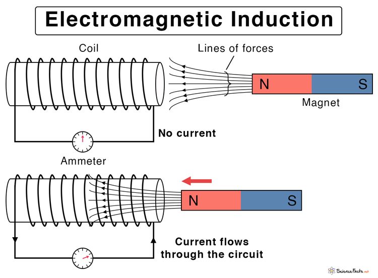
Electromagnetic induction is the phenomenon by which a changing magnetic field induces a voltage in a conductor. When a magnet moves through a coil, the changing magnetic flux through the coil induces a voltage across the ends of the coil.
According to Faraday’s law of electromagnetic induction, the magnitude of the induced voltage is proportional to the rate of change of magnetic flux through the coil. The faster the magnet moves, the greater the rate of change of magnetic flux, and the larger the induced voltage.
The induced voltage drives a current in the coil, which circulates to oppose the change in magnetic flux according to Lenz’s law. So when the north pole of a magnet approaches the coil, the induced current circulates so that its own magnetic field opposes the field of the approaching north pole of the magnet. Conversely, when the north pole of the magnet recedes from the coil, the induced current changes direction so as to oppose the receding north pole.
In summary, moving a magnet through a coil induces a voltage across the coil through electromagnetic induction. Lenz’s law describes the direction of the induced current, always opposing the change in magnetic flux.
Induced Current
When a magnet is moved in and out of a coil of wire, the changing magnetic field of the magnet passes through the coil and induces a current in the coil. This is known as electromagnetic induction. According to Faraday’s law of electromagnetic induction, the magnitude of the induced current in the coil is directly proportional to the rate of change of magnetic flux through the coil.
As the magnet moves into the coil, the magnetic field lines cut the coil windings, increasing the magnetic flux through the coil. This changing flux induces a current in the coil. The direction of the induced current will be such that it opposes the change in magnetic flux according to Lenz’s law. So the induced current flows in a direction to generate a magnetic field that opposes the increasing magnetic field of the magnet.
As the magnet moves out of the coil, the magnetic field lines cut the coil windings in the opposite direction, decreasing the magnetic flux. This changing flux again induces a current in the coil, but now in the opposite direction, opposing the decreasing magnetic flux.
The faster the magnet moves in and out of the coil, the greater the rate of change of magnetic flux, and the greater the magnitude of the induced current. The magnitude also depends on the number of coil turns – more turns means a larger induced current. So in summary, the induced current opposes changes in magnetic flux and its magnitude depends on the rate of flux change and the number of coil turns.
Induced Voltage
When a magnet is inserted into a coil, it generates a voltage across the coil. This is called induced voltage and occurs due to electromagnetic induction.
As the magnet moves through the coil, the magnetic field lines interact with the coil and change the magnetic flux through the coil. According to Faraday’s Law of Electromagnetic Induction, any change in magnetic flux through a circuit induces an electromotive force or voltage in that circuit.
The changing magnetic field generated by the moving magnet causes the magnetic flux to change and hence induces a voltage across the coil terminals. The magnitude of the induced voltage depends on the rate of change of magnetic flux.
Faster the change in magnetic flux, higher will be the induced voltage generated. The induced voltage causes a current to flow in the coil. This is called induced current. So the induced voltage is directly related to the induced current produced in the coil due to electromagnetic induction.
The induced current magnitude depends on the induced voltage as given by Ohm’s law. Higher the induced voltage, higher will be the induced current and vice versa for a given coil resistance.
Factors Affecting Induced Voltage
There are three main factors that affect the induced voltage when a magnet is moved inside a coil:
Speed of the Magnet
The faster the magnet moves through the coil, the greater the induced voltage. This is because a faster moving magnet causes the magnetic flux through the coil to change more rapidly. According to Faraday’s law, the faster the rate of change of magnetic flux, the greater the induced EMF or voltage.
Number of Coils
Using more coils wound together increases the induced voltage. Each coil experiences the changing magnetic field and contributes to the overall induced EMF. More coils means more wire cutting magnetic flux lines, resulting in a larger induced voltage.
Strength of the Magnet
A stronger magnet produces a stronger magnetic field. When a stronger magnet moves through a coil, it causes a greater rate of change of magnetic flux, leading to a larger induced EMF or voltage, according to Faraday’s law.
So in summary, faster magnet speed, more coils, and a stronger magnet all result in a greater induced voltage when putting a magnet inside a coil.
Transformers
Transformers are an important application that rely on the principles of electromagnetic induction. Transformers work by transferring electrical energy between two coils that are linked by a magnetic field. There are two main types of transformers:
Step-up transformers – These increase the voltage from the input coil to the output coil. They have the input coil with fewer windings than the output coil. As a result, the induced voltage in the output coil is greater. Step-up transformers are used at power plants to increase the voltage from the generator so it can be transmitted long distances over transmission lines.
Step-down transformers – These decrease the voltage from input to output. They have an input coil with more windings than the output coil. This results in a lower induced voltage in the output coil. Step-down transformers are used to reduce the high transmission line voltages to safer levels for distribution and use in homes and businesses.
Other common examples of transformers include those found in cell phone chargers, laptop power supplies, and voltage converters for international travel. In these cases, the transformer adjusts the voltage to the required level for charging batteries or powering devices.
Other Applications
The principle of electromagnetic induction has numerous practical applications beyond just coils and transformers:
Generators – Rotating magnets or coils can be used to generate alternating current via electromagnetic induction. This allows the generation of electricity from mechanical power, which is how most electricity is produced.
Inductors – Inductors use coils to store energy in magnetic fields and oppose changes in current. They are passive components used to filter signals, tune radio frequency circuits, and for many other purposes.
Electric Motors – Motors do the reverse of generators, converting changing magnetic fields into rotational force and motion. They rely on the interactions between magnetic fields and current-carrying coils.
Metal Detectors – Metal detectors use oscillating magnetic fields to induce eddy currents in metallic objects. This alters the magnetic field, which can be detected as a change in coil inductance or voltage.
Wireless Power Transfer – Changing magnetic fields can wirelessly induce current in nearby coils, which enables transferring power without wires. This has applications like charging electric vehicles and consumer electronics.
Conclusion
When a magnet moves through a coil, it produces a varying magnetic flux through the coil. This varying flux induces an electromotive force (emf) or voltage in the coil. According to Faraday’s Law of Electromagnetic Induction, the magnitude of the induced emf is equal to the rate of change of magnetic flux through the coil.
The induced emf causes a current to flow in the coil, known as induced current. The direction of the induced current depends on whether the magnetic flux is increasing or decreasing through the coil at that instant, as per Lenz’s Law. Several factors affect the magnitude of the induced emf and current, including the strength of the magnetic field, the speed of the magnet’s motion, the number of turns in the coil, and the coil’s area.
This phenomenon of electromagnetic induction is utilized in many applications such as electrical generators, transformers, and metal detectors. The induced voltage and current direction can be controlled by carefully designing the coil geometry and manipulating the external magnetic field.