What Is The Head In A Hydroelectric System?
What is the Head in Hydroelectric Power?
The head in a hydroelectric power system refers to the vertical distance between the intake where water enters the system and the turbine where electricity is generated. More specifically, head is a measurement of the hydraulic potential energy available to generate electricity based on the difference in elevation between the water source and water exit point.
As water flows from the intake to the turbine, gravitational potential energy gets converted into kinetic energy. The higher the vertical drop, or head, the greater the flow rate and kinetic energy of the water. This potential energy gets converted into rotational kinetic energy as it hits turbine blades, which then spin a generator to produce electricity. Essentially, the greater the head, the more power that can be generated from a hydro system for a given water flow rate.
Head is one of the most important factors in hydroelectric power generation. More head allows more power to be produced from the same amount of flowing water. Dams are often built to increase head by creating large reservoirs at higher elevations. Overall, harnessing as much vertical head as possible is crucial for optimizing the power output of a hydroelectric system.
Sources:
https://renewablesfirst.co.uk/hydropower/hydropower-learning-centre/head-and-flow-detailed-review
https://renewablesfirst.co.uk/renewable-energy-technologies/hydropower/hydropower-learning-centreold/what-is-head/
Hydraulic Head
Hydraulic head refers to the amount of mechanical energy that is available in water due to its elevation and pressure. It is a key concept in hydroelectric power generation as it determines the capability of water to produce hydroelectricity at a site.
Specifically, hydraulic head is the height difference between the headwater level and the tailwater level. The headwater level refers to the water surface upstream of the dam, while the tailwater level refers to the water surface downstream of the dam where water exits the turbines. The greater the height difference between these two points, the greater the hydraulic head.
According to the Energy Education Network, hydraulic head is calculated as:
Head = Elevation head + Pressure head
Where elevation head is the vertical height the water falls and pressure head is the water pressure converted to an equivalent water height. This hydraulic head measurement indicates the amount of potential energy available to drive the turbines for generating hydroelectricity.
Gross Head vs Net Head
In hydroelectric power systems, there are two main measurements of head: gross head and net head. Gross head refers to the total hydraulic head available in the system, measured as the vertical distance between the headwater level and the tailwater level (outlet of the turbine). It represents the maximum possible head that could drive the turbine. Net head accounts for the head losses that occur due to friction, turbulence, and changes in velocity as water flows through the system. It refers to the actual head acting on the turbine and is always lower than the gross head.
According to HydroCo, the net head is “the difference in Total Head between the Inlet Reference Section of a turbine and the Outlet Reference Section.” In other words, it factors in the reductions in head from the inlet to the outlet. Gross head does not account for these losses. As explained by HK Divede, “Net head is basically defined as the head available at the inlet of the turbine.”
The difference between gross and net head depends on the amount of head losses in the system. The greater the losses due to friction, changes in velocity, elbows, valves, and other components, the larger the difference between gross and net head. Optimizing the system design to minimize losses helps maximize net head and increase the power output of the hydroelectric plant.
Measuring Head
Head is typically measured in units of length, such as meters or feet. There are a few common methods for calculating head:
Using a surveying level or laser level to take elevation measurements at the intake and turbine locations. The difference in elevation is the gross head. This method requires accurate surveying but gives a precise head measurement (Source).
Using a pressure gauge or piezometer installed in a vertical pipe at the intake and turbine sites. The difference in water pressure translates to head, based on the density of water. This gives a good measure of net head (Source).
Using a flexible hose filled with water. By moving the hose between intake and turbine sites and observing the water level difference, you can directly measure head. This simple method works for approximating head (Source).
Head and Power Generation
The amount of power that can be generated from a hydroelectric system is directly proportional to the head of the system. The higher the head, the greater the potential energy and power output. As water falls from the higher elevation reservoir to the lower elevation turbine, it converts its potential energy into kinetic energy. This kinetic energy is then converted into electricity by the turbine and generator.
The relationship between head and power is described by the following formula:
Power (kW) = Flow (m3/s) x Head (m) x Gravity (9.81 m/s2) x Efficiency
Where:
– Flow is the volumetric flow rate of water through the turbines measured in cubic meters per second (m3/s)
– Head is the height difference between the reservoir and turbine measured in meters (m)
– Gravity is the acceleration due to gravity (9.81 m/s2)
– Efficiency accounts for any losses in the system
As the formula shows, for a given flow rate, doubling the head doubles the power output. Therefore, sites with higher heads have greater electricity generating capabilities. This is why hydroelectric dams are often built in mountainous regions where greater heads can be obtained.
The gross head is the maximum head available in the system. However, frictional losses in valves, pipes, and turbines reduce the head at the turbine. This effective head is called the net head. The net head must be used in the power equation to calculate actual power production.
Optimizing Head
Optimizing head is a key consideration when designing a hydroelectric power plant in order to maximize energy generation. There are several ways to optimize head:
Increase the vertical drop between the water intake and the turbines by selecting an appropriate site with natural topography. Building dams and reservoirs can also increase the head by creating an artificial height difference (Azad, 2020).
Minimize frictional head losses in penstocks and tunnels that carry water to the turbines through smooth surfaces and optimal diameters. This helps maintain a higher net head. Head losses can be reduced by 10-15% through penstock optimization (Sidorenko, 2019).
Regulate water flow based on energy demands to maintain ideal head levels. Using variable speed turbines that can operate efficiently across a range of heads can also help optimize energy output.
Consider the relationship between head and flow rate. As head increases, the flow rate can be reduced while maintaining power output. Designing turbines and generators to operate at a range of heads and flows allows maximizing energy across variable conditions.
Selecting the right turbine design based on the head classification (high, medium or low head) ensures efficient conversion of hydraulic energy. Kaplan turbines are well-suited for low heads while Pelton turbines perform best with high heads.
Overall, a hydroelectric plant’s head must be optimized based on site conditions and engineering design to maximize power generation.
Low Head vs High Head Hydroelectric Projects
Hydroelectric projects are often classified as either low head or high head based on the hydraulic head available. Hydraulic head refers to the vertical distance water falls to produce power. It is a measurement of the water pressure available to spin the turbines.
High head projects have an effective hydraulic head of over 100 meters. They utilize the potential energy in elevated reservoirs or waterfalls to maximize the water pressure on the turbines. High head projects can generate a large amount of electricity even with a low flow rate. However, they require expensive dams, tunnels, and pipelines to deliver water to the turbine house.[1]
Low head projects operate with a hydraulic head under 10 meters. They harness energy from rivers or man-made channels with a gentle slope. While low head sites do not produce as much power per unit of water, they can still generate electricity efficiently with high flow rates. Low head projects have lower civil engineering costs but may require more complex turbine designs.[2]
The optimal hydroelectric design depends on the natural topography and water resources available. High head and low head projects both have advantages that makes each suitable for different situations.
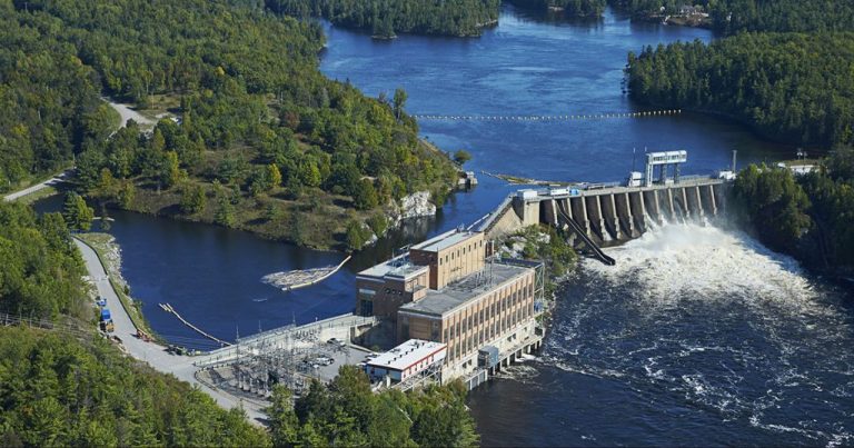
Headwater and Tailwater
The headwater is the water upstream of the dam in a hydroelectric system. It is the water that will flow through the dam to generate electricity. The level of the headwater depends on how much water is stored behind the dam.
According to a hydroelectric dam resource from Savree, “The headwater is located upstream of the dam and the tailwater downstream; the dam physically separates the headwater and tailwater. The headwater consists of a reservoir or lake where water can be stored.”1
The tailwater is the water downstream of the dam after it has passed through the turbines to generate electricity. The tailwater flows through the tailrace which carries it away from the power station.
As explained on the Energy Education website, “The tail race, containing tail water, is a channel that carries water away from a hydroelectric plant or water wheel. The water in this channel has already passed through the turbine and generated power.”2
The difference in elevation between the headwater and the tailwater is called the gross head. The larger the gross head, the more potential energy the water has to generate electricity as it falls from the headwater to the tailwater level. Optimizing and maximizing the head is important for efficient power generation.
Head Losses
Head losses in hydroelectric power systems occur due to friction and turbulence as water flows through the system. There are two main types of head losses:
- Major head losses occur due to friction in long lengths of piping like penstocks. Friction against the pipe walls causes energy to be lost. The longer the piping system, the higher the major head loss.
- Minor head losses occur at bends, valves, junctions, enlargements, contractions and other fittings. These cause turbulence and changes in velocity that result in localized energy losses.
There are several ways to minimize head losses in a hydroelectric system:
- Use larger diameter pipes and penstocks to reduce friction. This allows water to flow more freely.
- Avoid sharp bends in the piping and use long radius elbows instead. This reduces turbulence.
- Minimize the use of valves and fittings or use more efficient hydrodynamic designs.
- Line pipes and penstocks with smooth materials like PVC or HDPE. The smooth walls reduce friction.
- Maintain adequate penstock slopes to keep flow velocities in the optimal range.
Properly designing the system for the expected water flow and minimizing obstructions and turbulence can help reduce losses. This increases the net head at the turbine and improves power generation efficiency.
Case Studies
There are several interesting case studies of hydroelectric projects that were optimized based on the available head:
The River Bain Hydro Project in the UK was designed to utilize the 10m of hydraulic head identified in historic studies of the river. The project uses an Archimedes screw turbine optimized for low head sites to generate 140 kW of power (River Bain Hydro Project).
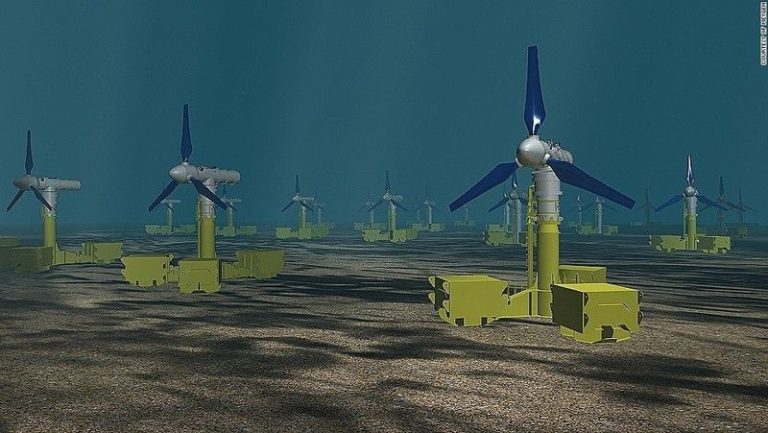
The Vortex hydrokinetic turbine was installed in a canal in Slovenia to take advantage of less than 2m of head. The helical design allows efficient power generation from ultra-low heads (Hydropower Case Study Collection: Innovative Low Head).
Idaho National Laboratory optimized conventional hydropower at a high head run-of-river site on the Niagara River, considering gross vs net head and hydraulic losses (Hydro Power – A Case Study).