What Is Electrical Flow Rate Called?
Introducing Electrical Flow Rate
Electrical flow rate refers to the rate at which electric charge flows in an electrical circuit. It is a fundamental concept in electrical engineering and physics. The standard unit for measuring electrical flow rate is ampere, commonly abbreviated as amp or A.
Electrical flow rate, also known as electric current, is a critical parameter that determines the behavior of electric circuits. The amount of current flow dictates the rate at which energy is transferred in a circuit. It also relates directly to the power consumed and generated in electrical devices.
Controlling and measuring current flow is essential for the proper operation of all electrical and electronic equipment. From large power systems that deliver electricity to homes and businesses to tiny integrated circuits powering our smartphones, they all rely on regulating current flow through their components and wires.
Understanding electrical flow rate enables engineering of safer, more efficient circuits and devices. It is key for optimizing power usage, preventing hazards like overheating, and transmitting signals or information via electricity.
In summary, electrical flow rate, or current, is a vital concept in electrical engineering and physics that underpins the performance of electrical systems and technologies we use every day.
Current
Electrical flow rate is referred to as electrical current. Electrical current is defined as the rate at which electric charge flows past a point or region. Simply put, current represents the amount of electrical charge moving through a conductor, such as a copper wire, each second. Current is measured in amperes or amps for short. An ampere is defined as one coulomb of charge passing a given point per second.
When voltage is applied across a conductor, it gives the charges energy and sets them into motion. The charges are electrons that are able to move freely in the conductor. The greater the voltage, the greater the force applied to the electrons, which results in a higher flow rate or current. Therefore, voltage and current are directly proportional. The higher the voltage, the higher the current will be.
Measuring Current
Current is measured in amperes or amps for short. An ampere is defined as the constant flow of electric charge at a rate of one coulomb per second. The ampere is part of the International System of Units (SI).
Some common units used to measure current include:
- Ampere (A) – The base SI unit.
- Milliampere (mA) – Equal to 1/1000 of an ampere.
- Microampere (μA) – Equal to 1/1,000,000 of an ampere.
- Kiloampere (kA) – Equal to 1,000 amperes.
Devices called ammeters are used to measure current. They are connected in series in a circuit to measure the flow of charge through a component or circuit as a whole. The reading indicates the magnitude of current through the ammeter, providing a snapshot of current at any given point.
Ohm’s Law
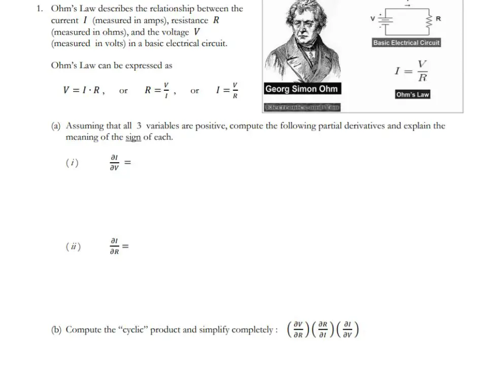
Ohm’s law describes the relationship between current, voltage, and resistance in an electrical circuit. It states that the current (I) flowing through a conductor is directly proportional to the voltage (V) applied and inversely proportional to the resistance (R) of the circuit. This can be represented by the formula:
I = V/R
Where:
- I is the current in amps (A)
- V is the voltage or potential difference in volts (V)
- R is the resistance in ohms (Ω)
So according to Ohm’s law, if we increase the voltage across a fixed resistor, the current will proportionally increase. Likewise, if we increase the resistance in a circuit with a fixed voltage, the current will decrease.
Ohm’s law is a fundamental relationship applicable to any circuit with conductive elements. It allows us to easily calculate the current, voltage, or resistance if we know two of the variables. Understanding this concept is key for analyzing and designing electrical circuits.
Direct Current vs Alternating Current
Electricity can flow in two ways – through direct current (DC) or alternating current (AC). The key difference between direct current and alternating current is that direct current flows in one direction only, while alternating current continuously changes direction.
In direct current, electricity flows in a constant direction from positive to negative. The voltage remains constant over time. Direct current is produced by sources such as batteries, solar cells, and fuel cells. Most electronic devices run on DC power.
In alternating current, the flow of electricity periodically reverses direction. The voltage alternates between positive and negative over time in the form of a sine wave. Alternating current is produced by rotating generators at power plants. Most power grids and household outlets provide AC electricity.
Some key differences:
- DC flows in one direction, AC changes direction periodically
- DC voltage is constant, AC voltage alternates between positive and negative
- DC comes from batteries, solar cells, fuel cells. AC comes from generators and power plants
- Electronic devices run on DC. Power grids and wall outlets provide AC
Understanding the differences between direct current and alternating current is important for working with electricity and electrical devices. While both have their uses, AC is the most common type of electricity for power transmission and household use.
Factors Affecting Current
There are several factors that affect the flow of electrical current in a circuit:
Voltage – Voltage is the electrical potential difference between two points in a circuit, measured in volts. A higher voltage will produce a higher current in a circuit. Voltage can be increased by adding more batteries to a circuit.
Resistance – Resistance, measured in ohms, opposes the flow of electrons in a circuit. A higher resistance in a circuit will result in a lower current. Resistance can be increased by using thicker wires, higher resistivity materials, or adding resistors.
Temperature – Increasing the temperature of a conductive material will cause an increase in electrical current. As temperature rises, the vibrational energy of atoms and electrons increases, allowing electrons to more easily flow.
Circuit Path – The easier it is for electrons to flow in a loop around the circuit, the higher the current will be. Using wider and shorter circuit paths decreases resistance and increases current.
Electromotive Force – Sources of electromotive force like batteries provide energy to move electrons through a circuit, producing current. More batteries or higher voltage sources will induce a greater electromotive force.
Applications
Current plays a vital role in the functioning of many electrical devices and systems that we use every day. Here are some examples of how current is applied:
-
Household appliances – Devices like refrigerators, microwaves, washing machines, etc. rely on the flow of current to operate motors, heating elements, control boards, and other components.
-
Lighting – Light bulbs glow due to the heating effect of current passing through a thin filament or semiconductor material inside them.
-
Electronics – All electronic devices and circuits like smartphones, computers, TVs, radios, etc. depend on regulated current flow through transistors, integrated circuits, and other components.
-
Industrial equipment – Motors, generators, transformers, and heavy machinery used in factories and plants require high electrical current flows to drive large mechanical loads.
-
Medical devices – Many medical instruments and equipment such as X-ray machines, MRI scanners, defibrillators, etc. utilize current for imaging, diagnosis, treatment, and monitoring of patients.
-
Vehicles – Automobiles, trains, aircraft, ships, etc. need currents to charge batteries, ignite fuel, power lights, run control systems, and operate electronic devices.
In summary, the controlled flow of electrical current enables the functioning of a wide variety of equipment and systems that we use in everyday life across many fields and industries.
Measurement Devices
There are several instruments used to measure current in electrical circuits and systems:
Ammeters are devices used to measure current in amperes. They are connected in series in a circuit to get an accurate reading and measure the amount of current flowing through it. Analog ammeters contain a small coil that deflects a pointer across a scale based on the strength of the magnetic field produced by the current. Digital ammeters use analog-to-digital conversion to provide a numerical readout.
Clamp meters are handheld devices that clamp around a wire to measure current without breaking the circuit. They use Hall effect sensors or current transformers to convert magnetic field strength into an electrical signal that can be displayed. Clamp meters are very convenient for taking quick measurements.
Shunt resistors are low-resistance precision resistors placed in series in a circuit. By measuring the voltage drop across the shunt, the amount of current flowing through can be accurately calculated using Ohm’s law. They allow current measurements without directly interrupting the flow path.
In addition, oscilloscopes display current waveforms plotted against time, while data loggers can record measurements for analysis. Proper calibration and technique is necessary for accurate current measurement.
Safety
Electrical current can be very dangerous if not handled properly. Here are some important safety precautions to keep in mind:
Use insulation – Make sure exposed conductors and terminals are insulated to prevent accidental contact. Rubber, plastic and ceramic are common insulating materials.
Use proper protective equipment – When working with electricity, wear rubber gloves and boots, safety goggles, and other protective gear as needed. This protects you from shocks and burns.
Check for live wires – Before working on electrical equipment, use a voltmeter or other tester to confirm wires are dead. Assume all wires are live until proven otherwise.
Turn off power – Lock out and tag out electrical systems before servicing to prevent accidental reactivation.
Limit access – Restrict access to electrical service panels and dangerous areas only to qualified personnel.
Connect proper grounding – Always ensure electrical systems and equipment are properly grounded to safely divert current in the event of a fault.
Address hazards – Correct any tripping hazards from cables and cords, overloading issues, faulty equipment or improper installations.
Following basic electrical safety principles is critical for preventing shocks, fires, explosions, and other dangerous electrical hazards. Safety should always be the top priority when working with electrical systems.
Conclusion
Electrical flow rate, known as current, is an important concept in electrical engineering and physics. Current is the directed flow of electrons through a conductor and is measured in amperes. Some key takeaways:
– Current is generated by voltage and regulated by resistance as described by Ohm’s law. It flows in closed loops through circuits.
– Direct current flows in one direction. Alternating current oscillates back and forth. Most power grids use AC.
– Factors like temperature, cross-sectional area and conductor material affect current flow. Higher temperature increases resistance.
– Applications of electrical current include electronics, electrical power transmission, electromagnetism and more. Ammeters, galvanometers and shunt resistors measure it.
– Safety precautions like circuit breakers, fuses and grounding protect against excessive current and its hazards like burns, fires and shocks.
In summary, current is the rate of electrical flow and a fundamental electrical engineering concept with many theoretical and practical uses. Understanding current and electrical principles enables innovation in electronics, energy and other fields.