What Is An Example Of A Potential Difference In Electricity?
Potential difference, also known as voltage, is a key concept in understanding electricity. It refers to the difference in electric potential between two points in an electric circuit. This difference in electric potential is what causes electric current to flow through the circuit.
Understanding potential difference is important because it allows us to predict and control the flow of electricity. Electricity powers the modern world, from small devices like phones to large infrastructure like power grids. By harnessing potential difference, we are able to generate, transmit, and use electricity for human benefit.
In this article, we will explain the basics of potential difference and other key electrical concepts. We will look at real-world examples to understand how potential difference drives electricity and makes our electronic devices function. A solid grasp of these core concepts empowers us to safely and effectively use electricity in our everyday lives.
Voltage
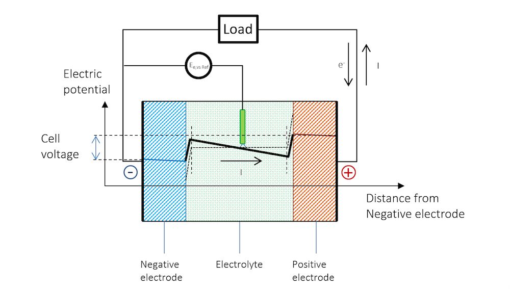
Voltage is the difference in electric potential between two points in an electrical circuit. It measures the “push” or “pressure” of electricity and is what causes current to flow through a circuit. Voltage is measured in volts and represented by the letter V.
When there is a difference in electric potential energy between two points, electrons will flow from the point of higher potential energy to the point of lower potential energy. This flow of electrons is what we call electrical current. So in essence, voltage is the driving force that pushes electrons through a circuit, enabling current to flow.
Voltage can be measured using a voltmeter connected across two points in a circuit. Since voltage is relative, the voltmeter will measure the difference in electric potential between those two points. The higher the voltage, the larger the potential difference and push on electrons between the two measurement points. Typical sources of voltage within circuits include batteries, power supplies, and generators.
Current
Current is the rate at which electric charge flows past a point in a circuit. It is measured in amperes (A). Current flows when there is a potential difference (voltage) that causes electrons to move through a conductor. The greater the voltage, the greater the current that flows. So there is a direct relationship between voltage and current – increasing the voltage increases the current, and decreasing the voltage decreases the current.
Current flows in the form of electrons moving through a conductor like a wire. These electrons are negatively charged particles inside atoms that are able to move from one atom to another. When voltage is applied across a conductor, it gives the electrons energy, causing them to move. The electrons flow from areas of lower potential (negative terminal) to areas of higher potential (positive terminal). This flow of electrons makes up the electric current.
The amount of current that flows depends on three factors: voltage, resistance, and the nature of the conductor. For a given voltage and conductor, increasing resistance reduces current, while decreasing resistance increases current. Conductors like copper have free electrons that can easily move, allowing more current to flow compared to resistors or insulators.
Resistance
Resistance is a measure of an object’s opposition to the flow of electric current. When current flows through a conductive material, the electrons moving through the material collide with atoms and ions present in the material, slightly heating it and slowing down the electron flow. Materials with high resistance restrict this flow of electrons more than materials with low resistance.
Resistance is what allows electronic components like resistors, as well as materials like metal wires, to regulate and control the current passing through a circuit. The higher the resistance, the more the material opposes the flow of electrons, reducing the amount of current for a given voltage.
The resistance of a material depends on several factors:
- Resistivity – An intrinsic property of the material that measures how strongly it opposes electric current. Materials like silver have very low resistivity, while rubber has very high resistivity.
- Length – Longer wires and components have more atoms and ions to collide with electrons, increasing resistance.
- Cross-sectional area – Thinner wires concentrate current flow into a smaller space, increasing resistance.
- Temperature – Rising temperature increases atomic vibrations, which increases collisions and resistance.
- Impurities – Impurities and defects disrupt the flow of electrons, increasing resistance.
By controlling these factors, the resistance of wires, components, and circuits can be precisely engineered to control current and voltage as needed for different applications.
Circuit Basics
An electrical circuit is a closed loop through which electric current can flow. A simple circuit contains three main components – a source of electrical energy, conductive wires, and one or more electrical components. The source of electrical energy, such as a battery or generator, provides voltage to drive the electric current through the circuit. Conductive wires, usually made of copper, provide a path for the current to flow throughout the circuit. Electrical components like resistors, capacitors, diodes, transistors, and integrated circuits are connected by the wires and regulate the flow of electrons.
For current to flow, a circuit must be complete with no gaps in the conductive path. If a circuit is broken by opening a switch or disconnecting wires, this creates an incomplete circuit or open circuit. In an open circuit, no current can flow even if voltage is present. To allow current to flow again, the gap in the circuit must be closed to complete the loop.
In a complete circuit, the amount of current flowing depends on the applied voltage and the total resistance of the components. Current will flow continuously in the loop as electrons move from the negative to positive side of the voltage source. The key to understanding circuits is recognizing the relationships between voltage, current, and resistance described by Ohm’s Law.
Ohm’s Law
Ohm’s Law is one of the basic principles that describes the relationship between voltage, current and resistance in electrical circuits. It was formulated by the German physicist Georg Ohm in the early 19th century.
Ohm’s Law is stated as:
V = I x R
Where:
- V is the voltage across a conductor (measured in volts)
- I is the current flowing through the conductor (measured in amps)
- R is the resistance of the conductor (measured in ohms)
This simple equation shows that the amount of steady current through a conductor is directly proportional to the voltage across the conductor, and inversely proportional to the resistance of the conductor.
In other words, for a given voltage, current is lower if the resistance is higher, and for a given resistance, current is higher if the voltage is higher. Resistance limits the flow of electrons through a conductor for a given voltage.
Ohm’s Law is a very useful tool for analyzing electrical circuits. It can help determine missing variables when two of the three quantities (voltage, current and resistance) are known. The law also explains why certain materials make good electrical conductors while others act as insulators.
Applications
Potential difference has many practical applications in our everyday lives. Here are some examples of how it is used:

Batteries – Batteries provide a potential difference between their positive and negative terminals. This potential difference causes current to flow through a circuit, powering devices like flashlights, smartphones, and laptops.
Electrical outlets – Standard US wall outlets provide 120V potential difference that allows electrical devices to operate when plugged in. The higher the potential difference, the more power can be delivered.
Tasers – Tasers and stun guns generate a high-voltage, low-current potential difference between their contacts to create an electric shock that temporarily incapacitates a person.
Defibrillators – Defibrillators apply a large potential difference across a patient’s chest to reset their heart rhythm during cardiac arrest.
Neurons – The axons of our nerve cells use brief potential differences to transmit electrical signals through the nervous system.
Touch screens – Touch screens have an electrical charge across their surface that gets disrupted when touched. This change in potential difference is measured to detect the location of the touch.
As you can see, potential difference is a fundamental electrical principle that enables many key technologies in our modern world.
Measuring Potential Difference
To measure the potential difference in an electric circuit, you need to use a voltmeter or multimeter. A voltmeter is designed specifically to measure voltage, while a multimeter can measure voltage, current, and resistance.
Using a multimeter is the easiest way to measure potential difference. Follow these steps:
- Set the multimeter to the voltage setting, usually denoted with a “V” symbol.
- Connect the multimeter’s red probe to the positive side of the component and the black probe to the negative side.
- Power on the circuit. The multimeter will display the voltage reading.
- Note the voltage reading. This is the potential difference across that component.
Be sure to connect the multimeter probes in parallel, not in series. Placing them in series would alter the circuit. The probes should not interfere with the flow of electricity.
When measuring potential difference, be careful not to touch exposed conductors, as high voltages can be dangerous. Refer to the multimeter manual for detailed safety precautions.
With a properly set up multimeter, measuring potential difference across various parts of a circuit is straightforward. The voltmeter reading indicates how much voltage exists between those two points in the circuit.
Safety
When working with electrical circuits, it’s important to take proper safety precautions to avoid electric shocks, burns, and fires. Here are some basic guidelines:
- Never work on live circuits – always turn off power and double check with a voltmeter before handling wires.
- Use insulated tools and test equipment to avoid accidental contact.
- Wear rubber soled shoes while working on circuits to avoid shocks.
- Keep one hand in your pocket when working on live equipment to prevent currents across the chest.
- Use GFCIs and circuit breakers to quickly cut power in the event of a short circuit.
- Keep flammable materials away from equipment that could spark.
- Tape down loose wires and use cable management to prevent tripping hazards.
- Work in well ventilated areas when soldering or dealing with batteries/chemicals.
- Use properly rated components – don’t use wires or fuses beyond their current rating.
- Connect equipment to properly grounded power sources.
Following basic electrical safety guidelines helps prevent injury and damage when working on circuits. Safety should always be the top concern whenever electricity is involved.
Conclusion
In summary, potential difference, also known as voltage, is an important concept in electricity and electrical circuits. It refers to the difference in electric potential between two points in a circuit, and is measured in volts. Potential difference is what pushes electrons through a circuit and allows current to flow. The greater the potential difference between two points, the greater the current that will flow.
Understanding potential difference is key to grasping other electrical concepts like Ohm’s Law and circuit design. It allows us to predict and control the behavior of electricity. Potential difference powers all of our electronic devices and appliances. By harnessing it through batteries, generators, and outlets, we are able to put electricity to practical use in our daily lives. Whether you are an electrical engineer designing circuits or simply trying to understand your home wiring, having a solid grasp of potential difference is essential.


