What Determines The Flow Of Charge?
Electric charge is a fundamental property of matter that exists in two types – positive and negative. Protons carry a positive electric charge, while electrons carry a negative electric charge. The SI unit for electric charge is the coulomb (C). When two charged particles interact, they exert forces on each other. The electric force between two charged particles depends on the magnitude of the charges, as well as the distance between them.
Like charges repel each other, while opposite charges attract. For example, two protons will repel each other because they both carry positive charge. However, a proton and an electron will be attracted to each other due to their opposite charges. The forces between charges are governed by Coulomb’s law. The electric force increases with greater charge magnitude, and decreases rapidly with increased separation between the charges.
Electric Current
Electric current is defined as the flow of electric charges in a conductor. It refers to the movement of electrons through a medium due to a potential difference applied across the conductor. Electric current is measured in amperes (A), named after French physicist André-Marie Ampère who contributed to the understanding of electromagnetism.
The direction of conventional current is from the positive terminal to the negative terminal, opposite to the actual direction of electron flow. Electrons are negatively charged subatomic particles that make up the current. When voltage is applied, electrons flow from negative to positive potential, but the current flows in the opposite direction by convention.
Electric current can be classified into two main types: direct current (DC) and alternating current (AC). Direct current flows consistently in one direction from positive to negative. Batteries provide a constant DC voltage with a fixed polarity. Alternating current periodically reverses direction, meaning the flow of charges changes back and forth. The voltage level also alternates from positive to negative in a periodic sinusoidal pattern. AC is the form of electricity delivered to businesses and homes.
Electric Potential Difference
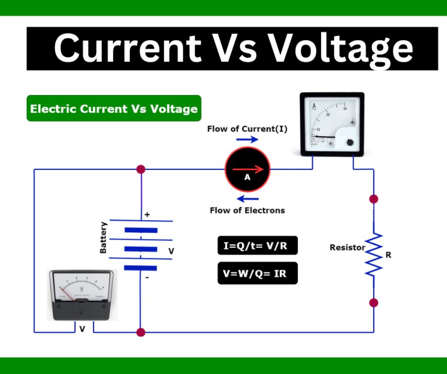
Electric potential difference, also known as voltage, refers to the difference in electric potential between two points in a circuit. It is measured in volts (V) and represented by the symbol V. Voltage represents the “push” or “pressure” that causes electric charges to flow in a circuit.
More specifically, voltage is generated by the power source in a circuit, such as a battery. The battery causes excess electrons to collect at the negative terminal, creating a high potential. The positive terminal has a shortage of electrons, creating a low potential. Connecting the terminals allows electrons to flow from high to low potential. The greater the difference in potential, the greater the voltage and the stronger the push of electrons in the circuit.
Voltage is essentially what provides the energy to move charges around a circuit. Without a voltage source like a battery, there would be no potential difference and no current flow. The amount of voltage impacts the strength of the current. Higher voltage allows more electrons to flow per second, resulting in a greater electric current. Voltage creates the electrical “pressure” that pushes charges through various components in a circuit.
Electromotive Force
Electromotive force (emf) is the energy provided per unit charge that causes current to flow through a circuit. It is measured in volts. There are several sources that can provide electromotive force in a circuit:
Batteries – Batteries provide emf through chemical reactions that cause a potential difference between the terminals. This potential difference provides the energy to move charges around the circuit when it is closed. The nominal voltage rating of a battery indicates the emf it provides.
Generators – Generators convert mechanical energy into electrical energy that appears as emf. The generator uses electromagnetic induction to create a potential difference as a conductor moves through a magnetic field. This induced emf causes charges to flow when the generator is connected in a circuit.
Solar Cells – Solar cells convert light energy into electrical energy and provide an emf. Photons in sunlight hit the solar cell material, knocking electrons loose and causing a potential difference between the front and back of the cell. This emf can drive current when the solar cell is connected in a closed circuit.
The electromotive force is the energy input that gives charges the potential to do work by moving through a circuit. It sets up the electric field that causes charges to flow. Without an emf source like a battery or generator, charges would not flow.
Electric Circuits
Electric circuits provide a closed path for charges to flow through. The main components of an electric circuit include:
- Battery – Generates the electromotive force (voltage) that drives the current.
- Connecting wires – Provide a path for charges to flow between the battery and other circuit components.
- Resistor – Limits the flow of current.
- Capacitor – Stores electric charge.
- Switch – Completes or breaks the circuit.
When the switch is closed, it completes the circuit, allowing current to flow from the high potential terminal of the battery, through the connecting wires and other components like resistors, returning to the low potential terminal of the battery. This creates a continuous loop or closed path for charges to move through.
The amount of current that flows depends on the electromotive force generated by the battery and the total resistance of the circuit. Resistors limit current, while capacitors can store charge and introduce delays in current flow. By carefully designing circuits with different combinations and values of components, we can control the path and magnitude of electric current.
Resistance
Resistance refers to how much something opposes the flow of electric current. When charges flow through a conductive material like a wire, they encounter friction that tries to slow them down. This friction that impedes the flow of charges is called resistance.
Resistance is measured in units called ohms, represented by the Greek letter omega (Ω). Materials with low resistance allow charges to flow easily, while materials with high resistance oppose current flow. For example, copper is a good conductor with low resistance, while rubber is an insulator with extremely high resistance.
Factors like the length and thickness of a wire affect its resistance. Longer wires have more resistance than shorter ones, and thinner wires have higher resistance than thick wires. Resistance also depends on the material’s resistivity, an intrinsic property indicating how strongly it resists flow of charges.
When current flows through a resistor, the collisions between charges and atoms causes the resistor to heat up. The higher the resistance, the more energy is lost as heat. Resistors are therefore used to limit current, divide voltages, and protect circuits from excessive current flow.
Conductors and Insulators
Materials can be classified according to how well they conduct electricity. Substances that readily allow the flow of electric current are called conductors. Metals like copper and aluminum are excellent conductors and are commonly used in electrical wiring. The free electrons in metal atoms can detach and move through the metal, allowing charge to flow.
Insulators are materials that resist the flow of electric current. Their atomic structure means they have very few free electrons able to move and carry charge. Examples of good insulators include rubber, plastic, glass and air. Insulating materials are very important for controlling the flow of current. They are used to protect and insulate electrical wires and components.
The resistance of a material depends largely on whether it is a good conductor or good insulator. Conductors like metals have very low electrical resistance, allowing current to flow freely. Insulators have extremely high resistance to current. This property makes insulators essential for preventing dangerous current flows, while conductors are vital for transmitting electricity.
Ohm’s Law
Ohm’s law is one of the most important principles in analyzing electric circuits. It states that the current (I) through a conductor between two points is directly proportional to the voltage (V) across the two points, and inversely proportional to the resistance (R) between them. This relationship can be written mathematically as:
I = V/R
Where I is the current in amps, V is the voltage in volts, and R is the resistance in ohms. This simple equation allows you to calculate any one of the three variables, if the other two are known. For example, if you know the voltage applied to a circuit and the resistance of the circuit, you can determine the current using Ohm’s law.
Some key points about Ohm’s law:
- It only applies to circuits or circuit elements with a single, linear resistance.
- The resistance must be constant, independent of voltage or current.
- For nonlinear devices like diodes, Ohm’s law does not apply.
- Temperature can change resistance, so R may not be constant if heating occurs.
- Ohm’s law is a simple but powerful tool for analyzing ideal resistors and circuits.
By applying Ohm’s law, you can understand the relationships between voltage, current, and resistance which is crucial for designing, constructing, and troubleshooting electric circuits.
Factors Affecting Current Flow
There are several factors that affect the flow of electric current in a circuit. These include:
Voltage Source/Electromotive Force (EMF)
The voltage source, or electromotive force (EMF), is the push or pressure that drives current through a circuit. A greater EMF allows more current to flow. Devices like batteries and generators create EMF.
Resistance
Resistance opposes current flow in a circuit. Materials like metal wires have some inherent resistance. Devices like resistors or filament bulbs also add resistance. Higher resistance reduces the current in a circuit.
Temperature
Increasing the temperature typically increases resistance, which reduces current flow. This is especially true for materials like metals. Lower temperatures reduce resistance and allow more current to flow.
Cross-Sectional Area
Materials with larger cross-sectional areas allow more current to flow. For example, thicker wires can carry more current than thinner wires made of the same material. Decreasing the cross-sectional area increases resistance and reduces current.
Applications of Current Flow
Current flow has many important applications in our modern world. Some of the major applications include:
Electronics
Current flow is used extensively in electronics and electrical devices. All electronic components like diodes, transistors, integrated circuits, etc. rely on current flow to operate. Consumer electronics like phones, computers, TVs, etc. would not function without utilizing current flow in their circuitry.
Motors and Generators
Electric motors operate on the principle of current flow through conductors in a magnetic field, which generates rotational motion. This allows electric motors to convert electrical energy into mechanical energy to drive pumps, fans, tools, etc. Generators work in reverse, converting mechanical energy into electrical current flow which can then be used to power devices.
Electrical Power Transmission
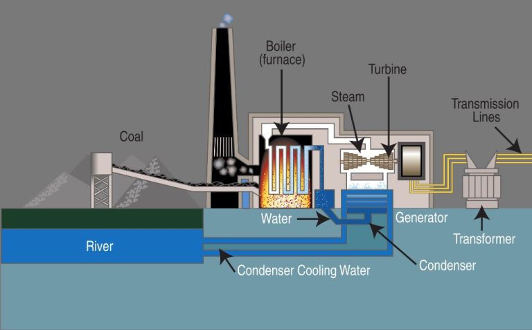
Large scale transmission of electricity over long distances relies on current flow through power lines. High voltage is used to enable efficient transmission over hundreds of miles. The current flow is then stepped down to safer levels for distribution and use.
Safety Devices
Fuses and circuit breakers are safety devices that interrupt the flow of current in case of overloads or short circuits. This prevents damage to equipment and prevents fires. These devices work by melting or tripping when current flow exceeds safe levels.