How Is Electricity Induced In A Generator?
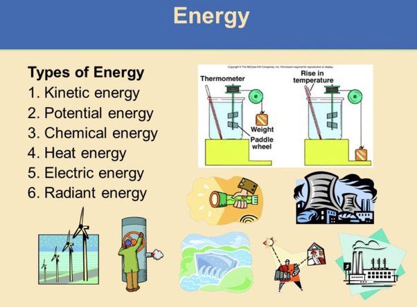
A generator is a device that converts mechanical energy into electrical energy. It does this through a phenomenon called electromagnetic induction.
The goal of this article is to explain how a generator works to convert the motion energy of spinning coils into usable electricity that powers our modern world. By understanding the basic components and principles that allow energy conversion, we can gain insight into this revolutionary technology at the heart of our electrified society.
Electromagnetic Induction
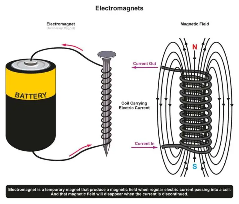
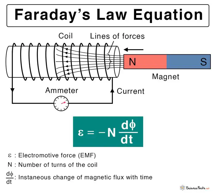
Electromagnetic induction is the process by which electricity is generated from the motion of a magnetic field relative to a conductor. It underlies the operation of generators, transformers, and electric motors. Electromagnetic induction was discovered in 1831 by Michael Faraday and is summarized by Faraday’s law of induction.
Faraday’s law states that the electromotive force or EMF (voltage) induced in a closed circuit is proportional to the rate of change of magnetic flux through the circuit. In other words, a change in magnetic field generates an electric current. This occurs because of the link between electricity and magnetism. The faster the magnetic field changes, the greater the induced EMF.
In a generator, mechanical energy from a moving part like a turbine is used to rotate a magnet within a coil of wire. This motion causes the magnetic field to change relative to the coil, inducing an EMF according to Faraday’s law. This EMF in turn drives an electric current in the wire. So the generator converts kinetic energy to electrical energy through electromagnetic induction.
Basic Generator Components
Generators have some basic components that work together to convert mechanical energy into electrical energy through electromagnetic induction. The main components are:
Rotor
The rotor is the rotating part of the generator. It has conductors, usually copper or aluminum windings, that rotate within the magnetic field created by the stator. As it rotates, it induces a voltage in the windings due to electromagnetic induction. This creates the output electricity from the generator. The rotor connects to the prime mover or turbine that powers it.
Stator
The stator is the stationary part of the generator. It contains a set of electrical conductors, usually copper windings, that are arranged to form a stationary magnetic field when energized with direct current through the exciter. The magnetic field produced by the stator windings induces a voltage in the rotor windings as they rotate past it.
Exciter
The exciter is a smaller generator that provides direct current to the stator windings to produce the magnetic field. It has separate windings connected to rectifiers that convert its alternating current output to DC for the stator. The exciter allows control of the strength of the magnetic field, which regulates the output voltage of the generator.
Prime Mover
The prime mover is the external mechanical force that rotates the rotor, usually a turbine turned by high-pressure steam, flowing water, wind, or combustion gases. The rotational kinetic energy is converted into electricity by the generator. The prime mover must turn the rotor at a constant speed for steady electrical output.
AC and DC Generators
Generators produce electricity in one of two ways: alternating current (AC) or direct current (DC). In an AC generator, the electric current reverses direction many times per second. The current first flows in one direction in the wire and then flows in the opposite direction. The number of times per second the current changes direction is measured in Hertz (Hz), and a typical AC generator runs at either 50 Hz or 60 Hz.
In contrast, in a DC generator, the current flows in only one direction in the wire. Once the current starts flowing in one direction, it continues flowing that way steadily. AC and DC generators work on the same general principles of electromagnetic induction – the process of generating voltage by moving a conductor through a magnetic field. However, there are important differences between AC and DC generators in terms of construction and operation.
AC generators have slip rings that allow current to be drawn from the rotor windings while allowing the rotor to spin freely. Brushes connect the slip rings to external loads. In a DC generator, a commutator is used instead of slip rings to convert alternating current in the rotor to direct current in the external circuit. DC generators are mechanically simpler than AC generators but can only supply DC power. AC generators can supply power to AC devices or be rectified to produce DC power if needed.
How a Simple DC Generator Works
A simple DC generator works through the process of electromagnetic induction to convert mechanical energy into electrical energy. Here is a step-by-step walkthrough of the process:
1. There is a magnetic field generated by an electromagnet or permanent magnets around the outside of the generator. This magnetic field is stationary and does not move.
2. Inside the generator, a coil of wire spins or rotates through the magnetic field. This rotation is driven by some external mechanical force, like a turbine, engine, or even hand cranking.
3. As the coil rotates through the magnetic field, the motion of the coil cuts across the magnetic field lines. This motion generates – or induces – a voltage in the coil through electromagnetic induction.
4. The induced voltage causes electrons in the coil to move and an electric current to start flowing through the coil. Metal contacts called brushes connect to the rotating coil and transfer the current flow out to an external electrical circuit.
5. The direction of the induced current reverses every half rotation as the coil spins, generating an oscillating or alternating current. A split-ring commutator switches the direction to produce a unidirectional or direct current.
6. The electrical load determines the strength of the current. Heavier loads require stronger electromagnets or permanent magnets to sustain adequate current flow against the increased resistance.
So in summary, the rotational mechanical energy is converted into electrical energy thanks to the generator’s electromagnetic induction process. This allows portable electricity generation from sources like wind, water, engines, and more.
AC Generator Operation
Alternating current (AC) generators work on the principle of electromagnetic induction to produce alternating current electricity. Inside an AC generator, a magnetic field is generated by either electromagnets or permanent magnets. This magnetic field is rotated mechanically by some external force, typically a turbine powered by water, steam, wind, or some other energy source.
As the magnetic field rotates around a coil of wire called the armature, the magnetic field induces a voltage in the coil through electromagnetic induction. The induced voltage causes an alternating current to flow through the wire as the magnetic field passes the coil first in one direction, then the other. Since the magnetic field is constantly rotating, the direction of the voltage and current alternate in a sinusoidal pattern, producing AC electricity.
The speed at which the magnetic field rotates determines the frequency of the alternating current. For example, in a 60 Hz generator, the magnetic field rotates at 3600 rpm (revolutions per minute). The number of loops in the armature coil helps determine the voltage level. More loops induce a higher voltage. Therefore, by designing the generator with the right number of pole pairs and armature loops, desired voltage and frequency can be generated.
Excitation Systems
The purpose of the excitation system in an AC generator is to induce a controllable DC current into the rotor winding, which generates the rotor magnetic field. This allows active control of the generator output voltage. There are several types of excitation systems used in generators:
Direct Current (DC) Excitation – Uses a DC generator connected directly to the main generator rotor. Simple and low cost, but lacks voltage regulation ability.
Alternator Excitation – An auxiliary internal alternator that generates AC power, which is rectified to DC for excitation. Provides good voltage control.
Static Excitation – Uses solid-state electronic components to control rotor excitation. Allows very fast and precise voltage regulation by digitally controlling excitation levels.
Modern generators use static excitation systems for optimal voltage regulation. The digital controller monitors voltage output and dynamically adjusts excitation levels to maintain steady voltage during load changes. Some systems even allow remote excitation control for grid stabilization.
Powering the Generator
The mechanical energy needed to spin the rotor inside a generator comes from an external source called the “prime mover.” There are several different types of prime movers that can be coupled to generators to produce electricity:
Steam Turbines
The most common prime mover for large-scale generators is a steam turbine. In a steam turbine, high-pressure steam produced in a boiler spins a turbine that is connected to the generator. The steam causes the turbine blades to rotate, which turns the rotor inside the generator. Steam turbines provide a reliable and efficient way to convert heat energy into rotational kinetic energy.
Gas Turbines
Gas turbines burn fuel like natural gas to generate a stream of hot gases that spin the turbine blades. The turbine is connected to a generator to produce electricity. Gas turbines offer advantages like lower startup times compared to steam turbines. They are commonly used for peaking power plants.
Internal Combustion Engines
Internal combustion engines like diesel engines can also be coupled to generators. The turning crankshaft of the engine spins the generator rotor to produce electricity. These systems are useful for small-scale distributed power generation. Diesel engine generators provide backup power generation for many facilities.
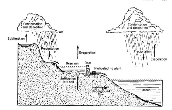
Hydropower Turbines
Flowing or falling water can spin hydraulic turbines that are connected to generators. Different types of hydropower turbines include Kaplan, Francis and Pelton turbines. Hydropower provides renewable and emission-free electricity generation.
So in summary, common prime mover options for generators include steam turbines, gas turbines, internal combustion engines and hydropower turbines. The mechanical power from these rotation sources gets converted into electrical power by the generator.
Generator Efficiency
The efficiency of a generator refers to how much of the mechanical energy input is converted into electrical energy output. There are several factors that impact the efficiency of this energy conversion in a generator:
Electrical Resistance
The windings and conductors in a generator have inherent electrical resistance. As current flows through these resistive components, some energy is lost in the form of heat. Minimizing the resistance of generator windings helps improve efficiency.
Friction and Windage Losses
The moving parts of a generator experience mechanical friction and windage losses. Improving lubrication and reducing the air gap between rotor and stator can minimize these mechanical losses.
Magnetic Losses
Changing magnetic fields in the generator induce eddy currents and hystersis losses in the iron core of the generator. Laminated core construction and improved magnetic materials help reduce these magnetic losses.
Electrical Load
Generator efficiency varies based on the electrical load demand. Peak efficiency is usually between 50-90% of full rated load. Operating too far below the optimal power output reduces efficiency.
Power Factor
The power factor of the electrical load affects the apparent power output. Optimizing power factor close to unity minimizes reactive power flows, thereby increasing real power output and generator efficiency.
By accounting for these factors, generator design and operation can be optimized to maximize the efficiency of converting mechanical rotation into electrical power.
Conclusion
Generators are a critical technology that allows us to convert mechanical energy into useful electrical energy. This process of electromagnetic induction, discovered by Michael Faraday, enables generators to induce an electrical current by rotating conductive coils within a magnetic field. While the basic principles have remained the same, generators have evolved to become more advanced and efficient.
The major components of a generator include a rotor, stator, and excitation system. The rotating motion of the rotor induces a voltage on the stator windings, which can be tapped off as electrical power. Generators may produce either direct current (DC) or alternating current (AC), with key differences in their construction and operating principles. Modern AC synchronous generators with brushless excitation systems are predominant today due to their superior efficiency and reliability.
Optimizing generator design requires managing tradeoffs between efficiency, durability, and cost. But the ability to convert mechanical power from sources like water, wind, steam, or gas turbines into usable electricity has been transformative for society. Generators have enabled widespread electrification and provide electricity virtually anytime it’s needed. Our modern way of life depends critically on the continuous supply of electrical power that generators provide through Faraday’s elegant concept of electromagnetic induction.