How Does Electricity Flow In A Current?
Electric current is defined as the flow of electric charges in a conductor. Understanding how electric current flows is crucial for harnessing electricity safely and effectively in our everyday lives.
Electric current involves the orderly movement of electrically charged particles called electrons. Current flows when there is a voltage – a difference in electric potential energy – applied to a conductor. This causes electrons to move from areas of higher potential energy to lower potential energy.
The key principles governing current flow include:
- Electric potential – the amount of potential energy available for electrons to do work
- Conductors and insulators – materials that allow or resist the flow of electrons
- Electric circuits – closed loops allowing electrons to flow continuously
- Electromagnetism – the relationship between electricity and magnetism
Understanding these basic concepts allows us to harness electric current for power, communications, computing, and countless other applications that are indispensable in the modern world.
Electric Charges and Electric Potential
Electricity arises from the movement of charged particles. Atoms contain positively charged protons in their nucleus and negatively charged electrons orbiting around the nucleus. Materials can gain or lose electrons, becoming positively or negatively charged. Like charges repel each other, while opposite charges attract. This interaction creates an electric field.
The difference in electric potential between two points, typically measured in volts (V), is called voltage. Voltage is created by an electric field, and results in the motion of charged particles. The greater the electric potential difference, the stronger the electric field, and the greater the flow of charge. For current to flow, there must be a complete circuit with an electric potential difference.
Positive electric charges naturally move towards lower potential, while negative charges move towards higher potential. Connecting points with different charges creates a potential difference. This difference in electric potential is measured in volts, and drives the motion of charges.
Conductors and Insulators
For electricity to flow, the material it travels through must allow the movement of electric charges. Materials that allow charges to flow are called conductors. Metals like copper and aluminum are good electrical conductors. In metals, some electrons are loosely bound and can move freely through the material.
Insulators are materials that resist the flow of electric charges. Examples of good insulators include rubber, plastic, wood, and air. In insulators, the electrons are tightly bound to atoms and cannot move freely. Insulators are used to coat wires and cables to prevent electric shocks. They are also used to separate different components in electrical circuits and prevent short circuits.
The ability for a material to conduct electricity depends on its molecular structure and bonding. Conductors have mobile electrons that can carry charge while insulators have tightly bound electrons that cannot move. Understanding conductors and insulators is key to controlling and directing the flow of electricity in circuits and devices.
Electric Circuits
Electric circuits provide a continuous closed path for electric current to flow. For current to flow, there must be a complete loop so that the moving charges can return to where they originated. This closed loop is typically formed by connecting various circuit components with conductive wires. Some key components found in electric circuits include:
- Power Source – This is necessary to push or pull electrons and maintain the electric current. Common power sources include batteries, solar cells, generators, etc.
- Wires – These provide a path for electrons to flow. Wires are made of highly conductive materials like copper.
- Resistors – These components restrict the flow of current. Different resistor values can be used to control current flow as needed for a given application.
- Switches – Allow parts of a circuit to be opened or closed as needed to turn current flow on or off.
- Capacitors – Store and release electric charge. Can be used to regulate power.
- Diodes – Allow current to flow in only one direction.
When connected properly in a complete loop, electric charges are able to flow continuously from the power source through the various circuit components and back to the power source. This cyclic closed path flow is what defines an electric circuit.
Current Flow in Wires
When a voltage is applied across a conductor like a wire, it causes the electrons within the wire to move. However, the electrons do not actually travel along the wire from end to end. Instead, they repeatedly collide with atoms in the conductor, transferring some kinetic energy with each collision. This causes what’s known as electron drift, where electrons move slowly in one general direction while still randomly vibrating and changing speeds. The drift velocity of electrons in a conductor is actually very slow, on the order of millimeters per second.
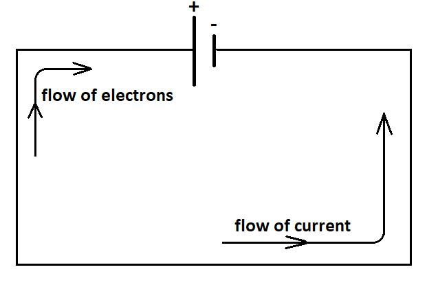
While electrons themselves slowly drift one way, the electric current flows in the opposite direction, from areas of excess positive charge to areas of excess negative charge. So conventional current is said to flow from the positive terminal to the negative terminal of a voltage source like a battery, which is opposite to the electron drift direction. This is an artifact from early electrical studies before the electron’s charge was understood, but the convention of positive-to-negative current direction remains in use today.
Factors Affecting Current
There are three main factors that affect the flow of electric current in a circuit: voltage, resistance, and current. Their relationship is described by Ohm’s Law, which states that the current flowing through a conductor is directly proportional to the voltage applied, and inversely proportional to the resistance of the circuit.
Voltage (V) is the electric potential or “push” that causes electrons to flow through a circuit. The higher the voltage, the greater the flow of current. Resistance (R) opposes current flow. It is provided by the material of the wires and other components in the circuit. Materials with low resistance allow current to flow easily, while materials with high resistance impede the flow. Current (I) is the rate of flow of electric charge, measured in amperes (A). According to Ohm’s Law:
V = IR
Where V is voltage, I is current, and R is resistance. This means that for a given voltage, increasing the resistance reduces the current, while decreasing the resistance increases the current.
The resistivity of different materials varies widely and depends on their molecular structure. Metals tend to have very low resistivity, allowing current to flow freely. Insulators like glass, rubber and plastics have very high resistivity and obstruct current flow. Semiconductors such as silicon and germanium fall somewhere in between. Factors like temperature can also affect a material’s resistivity.
Alternating and Direct Current
Electricity can flow in currents in two main ways – direct current (DC) and alternating current (AC).
In direct current, the electricity flows consistently in one direction from the power source through the circuit. The current does not change direction at all. Batteries provide DC power.
In alternating current, the direction of the flow of electrons switches back and forth periodically. The current repeatedly reverses between positive and negative over time. Most power plants and utility systems provide AC power by generating current that alternates directions at a rate of 60 cycles per second, or 60 Hz.
AC current has some advantages over DC. It’s easier to increase and decrease the voltage of AC power using a transformer. This allows AC power to be transmitted over long distances through power lines. AC can also power electric motors. So most appliances and household devices run on AC even though batteries provide DC.
Measuring Current
There are two main ways to measure electric current in a circuit: using an ammeter or a clamp meter. An ammeter is connected directly into the circuit and measures the current flowing through it. Ammeters work by utilizing a shunt resistor, which produces a small voltage drop proportional to the current. This voltage is measured and calibrated to display the current value. Clamp meters operate differently – they don’t need to connect to the circuit. Instead they work by using a current transformer with a magnetic core that opens up. When clamped around a wire, they can measure the magnetic field produced by the current and use that to calculate current. Clamp meters are especially useful for measuring current in hard to reach places or live wires, while ammeters provide a more precise reading but are more invasive to install.
Practical Applications
Electricity flowing through wires enables many of the technologies we use every day.
One key application is power transmission. Generators at power plants produce electricity that gets stepped up to high voltages. This allows the current to flow through transmission lines with minimal power loss over long distances to substations. There, the voltage gets stepped down for safe distribution to homes, businesses, and factories.
Electronics and appliances also rely on electric currents. From computers to refrigerators to electric toothbrushes, they contain components like resistors, transistors, and integrated circuits that control and alter the flow of electrons. This allows them to perform useful functions.
Of course, safety is paramount when working with electric currents. Wires must be properly insulated to prevent shocks. Circuit breakers and fuses help prevent overheating and fires. It’s important to use grounded outlets and avoid overloading circuits. Education on electrical hazards is essential.
In summary, the ability to generate, control, and safely transmit electric current has enabled innovations that shape modern life. However, respect for its dangers is crucial.
Conclusion
In this overview of how electricity flows in a current, we explored some key principles that govern the behavior of electric charges. We discussed how free electrons in a conductor can move under the influence of an electric field, creating an electric current. The flow of these charges is what allows electrical energy to be transmitted and put to practical use.
Crucially, we learned that the current in a circuit depends on the voltage applied and the resistance of the conducting material. Resistance arises from collisions between moving electrons and atoms in the conductor, impeding the flow. Ohm’s law describes the mathematical relationship between current, voltage and resistance.
We also covered the differences between alternating and direct currents, and the ways to measure current flow. Understanding the fundamentals of electric current empowers us to better utilize electricity safely and effectively in everyday applications.
Electricity underpins so much of the modern world. Being able to comprehend the invisible flow of charges allows us to harness this phenomenon to build and operate electrical devices and systems. A solid grasp of currents and circuits provides an important foundation for electrical engineering and design.